Project Description
Main Project Image
The project owner hasn't added main project image yet.
Project description
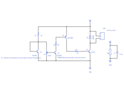
This circuit is practical to enable a automatic cooling to a system, by monitoring a temperature of a heat source (e.g. heat sink) and automatically controlling the speed of a DC Fan.
The circuit measures temperature difference by comparing a voltage drop of a transistor (Q1) with a base-emitter of a hot transistor (TSENSE).
The transistor Q1 is used as a reference temperature, and it must be positioned away from the heat source to ensure that it is kept at ambient temperature. The transistor Q2 TSENSE is mounted externally and must be thermally bounded to the heat source (e.g. use thermal paste and clamp it to the heat sink).
Q2 should not conduct when the temperature monitored is below a set threshold (P1), the base-emitter voltage of Q2 decrease by 2mV per degree C. Once the voltage is below the level set by P1. Q2 starts to conduct and the fan starts to spin up. The speed of the fan increase as the temperature increases in a linear fashion.
The absolute maximum temperature is 150ºC.
----
For use with bigger fans replace Q3 with a transistor with the appropriated ratings. Some alternatives are BD135 or a darlington TIP120/122 (a darlington transistor will ramp up to full RPM speed more quickly due to higher gain).
BC547 can also be used as a replacement for Q1 and Q2.
Gallery
The project owner hasn't added any images yet.
Design Files
Embed Code
Component (12)
Qty
Description
